‏إظهار الرسائل ذات التسميات هندسة. إظهار كافة الرسائل

Do Not Energize Oil-Filled Transformer Without Performing These 15 Tests and Checks!

,Do, Not, Energize, Oil,-Filled, Transformer, Without, Performing, These, 15, Tests, and, Checks!

Obligatory Checklist

The following tests and checks should be performed at a minimum to ensure that the transformer is ready to be energized. Do not energize the transformer without performing these tests and checks.
If any of below explained tests fail and transformer is energized anyway, it may lead to the serious hazard, and that’s not good. That’s not what we want.
Let’s see these 15 tests…

1. Insulating Fluid Test

Draw a fluid sample and test its dielectric strength. Dielectric strength of new fluid should be 26 kv or greater.

The breakdown voltage indicates how well insulating oil can withstand an electrical load and is therefore decisive for the operational efficiency of a transformer. The breakdown voltage is measured according to VDE 0370 part 5 (IEC 60156); photo credit: SIEMENS

2. Pressure Test

Check the transformer tank for leaks by pressurizing the tank with dry air or dry nitrogen through the pressure test fitting to a pressure of 3 to 4 PSIG. let the tank stand under pressure for one to two hours, then examine the tank and fittings for leaks. leaks above the fluid level can be detected by applying soap solution to all welds, joints, pipe fittings, and cable connections.
Upon completion of this test, reduce the internal pressure to 1 or 2 PSIG.

Repairing transformer oil-tank for leakage (photo credit: khia.belzona.com)

3. Insulation Megger Test

Perform a 1000-volt Megger test and a power factor test to ensure that none of the windings is grounded.

Regular insulation testing is one of the most cost effective methods of identifying aging of transformer

4. Ratio Test

Perform a ratio test at each tap position to ensure that transformer coil ratios and tap changer connections are correct.

5. Continuity Test and Resistance Test

Perform a continuity check on each winding. Measure the winding resistance of each winding and compare results to factory test values.
An increase of more than 10% could indicate a loose internal connection.

6. Line Connections

In preparation for making line connections, check to make sure that all mating connector surfaces are clean and smooth. Connections must be tightened appropriately to prevent overheating and possible subsequent failure of the connection.
Connections to should be made with care to avoid placing undue stress on the bushings.

Oil-filled transformer bushings (photo credit: khia.belzona.com)

7. Tap Changer Setting

Check the tap changer setting to ensure it is set to the proper position for the required voltage. 

On-Line Oil Filtration for Load Tap Changer Compartment (photo credit: velcon.com)

8. Delta/Wye and Series/Multiple Switch Settings

Check delta/wye and series/multiple switch settings to make sure they are set correctly.
If these connections are made using an internal terminal board, check to ensure that these connections are made properly according to the chart on the transformer nameplate.

GE distribution transformer nameplate (photo credit: tucsontransformer.com)

9. Grounding

Check to ensure that the transformer tank is permanently and effectively grounded. The transformer tank ground pad is located near the bottom of the tank.

10. Wiring

Check wiring of control and alarm circuits (if provided) to make sure there are no loose connections and no damage to insulation.

Oil-filled transformer terminal box

11. Fluid level


Figure 1 – Liquid Level Gauge


Check to make sure the fluid level as indicated by the fluid level gauge is as follows:
The fluid level gauge indicates the fluid level inside the tank. The transformer tank is filled with fluid at the factory to the normal level at a reference temperature of 25°C.

12. Tank Finish

Check all painted surfaces to make sure that there is no damage or corrosion.

13. Bolted Connections

Check all bolted connections for tightness.

Oil transformer bolted connections (photo credit: polywater.com)

14. Tools

Check to make sure that all tools and equipment are accounted for and have been removed from the transformer.

15. Fluid Temperature

Read the fluid temperature gauge and make sure the temperature is no lower than minus 20°Cbefore the unit is energized.

Figure 2 – Liquid Temperature gauge


Reference: Installation, Operation, and Maintenance of Medium Power Substation Transformers – Howard Industries

ثلاثة تطبيقات لللتصميم الكهربائي بنسختها الاصلية مجاناً

ثلاثة تطبيقات للتصميم الكهربائي بنسختها الاصلية مجاناً


نقدم لكم اليوم في هذه التدوينة ثلاثة تطبيقات بنسختها الاصلية للتصميمات والحسابات الكهربائية قيمتها يتجاوز 100 ريال تجدوها مجاناً على مدونة المهندس لتحميل التطبيقات اضغط على الصورة.

1- Electrical Calc Elite Electric

Great for Electrical Contractors, Designers, Engineers, Electricians, Maintenance Inspectors, Planners, Builders, and Lighting Specialists. The Electrical Calc Elite™ allows you to solve code-related problems quickly and accurately...the most common National Electric Code tables are now at your fingertips!
Electrical Calculations
• Wires Sizes
• Voltage Drop on Wires
• Conduit Sizing
• Ohm's Law
• Kirchhoff's Law
• Motor Full-Load Amps
• Power Factor and Motor Efficiency
• Fuse and Breaker Sizes
• Service and Equipment Grounding Sizes
• Electrical Unit conversion
• Parallel Resistance
• Circular MILs Wire
• NEMA starter size
• NEC® references for calculations

2- Electrician Calculator Pro
Electrician Calculator Pro - National Electric Code (NEC) compliant calculator for electricians, engineers and electrical professionals, electrical contractors, designers, lighting experts, inspectors, maintenance personnel and builders!
Compliant with NEC 2014, 2011, 2008, 2005 and 2002, and future updates are FREE!
Forget about complicated key combinations normally required for NEC calculators! With this app you'll be able to perform the following calculations in a straightforward way:
• Voltage Drop
All voltage drop calculations use NEC chapter 9 table 8 values (either stranded or unstranded), and ambient temperature is taken into consideration as per NEC chapter 9 table 8 FPN 2.
• Find voltage drop (in volts and percentage).
• Find the maximum cable length given a required voltage drop and wire gauge (for single and three phase circuits).
• Find the minimum wire gauge given a required voltage drop and distance (for single and three phase circuits).
• Ampacity
Ampacity calculations use NEC tables 310.16 and 310.17 to find maximum ampacity or minimum wire gauge. The correction factor for temperature is used in these calculations.
• Find the minimum wire gauge given an amps value and ambient temperature (can specify if it will be in a raceway or free air).
• Find the maximum ampacity of a cable given its gauge, the ambient temperature, and if it is in a raceway or free air.
• Conduit sizing and conduit fill
Conduit and cable diameters are obtained from the tables in NEC chapter 9. Maximum fill percentages are obtained from NEC chapter 9 table 1.
• Find the minimum size conduit given the gauge and number of cables.
- Can specify the following conduit types: EMT, ENT, FMC, IMC, LFNB, LFNA, RMC, PVC-80, PVC-40 / HDPE, PVC-A, PVC-EB.
- Can specify the following insulation types: THHN, THWN, THWN-2, THW, THHW, THW-2, TW, XHH, XHHW, XHHW-2, RHH, RHW, RHW-2.
• Find the maximum amount of cables that can be used, given conduit size and type, and cable gauge and insulation.
• Motor full load current
Motor full load current values are obtained from NEC tables 430-247, 430-248, 430-250 in chapter 9.
• Find the motor full current load for DC motors, single phase, squirrel cage, wound rotor, and synchronous electrical motors from 1/4HP to 200 HP.
• Grounding conductor
Find the grounding conductor for service entrances and equipment, as per NEC tables 250-66 and 250-122.
• Capacitor KVARs
Find the capacitor KVARs that must be connected to the system in order to correct low power factors caused by inductive loads.
• Power cost
Estimate the financial cost of running a specific load. You enter your KWH rate, the load in KW, and the hours spent with the load connected, and the calculator will return the cost. You can select your own currency from the Preferences section.
                           
3- Electrical Pro


A great tool for electrical engineers and electricians.
This app is a compilation of five sub apps that use the 2008/2011/2014 National Electric Code (NEC).
Bury Depth:
This will calculate the depth needed to bury a line.
Box Conduit Fill Pro:
This will calculate:
The maximum wires in a conduit
The minimum box size
The minimum conduit/nipple size
Fault Calculator Pro:
This will calculate:
A fault over a line
A fault through a XFMR
The bracing de-rate factor for a utility XR ratio
Motor Calculations:
Locked Rotor Amps
NEC Motor Table Look-up
Voltage Drop Pro:
This app will calculate:
The voltage/percent drop for a wire
Minimum wire size for a given percent drop
Max wire length for a given percent drop
Max amps for a given percent drop
The impedance of the wire based on the inputted values
Click the green "Voltage" label for custom voltages
Wire Ampacity Pro:
This app will calculate:
The minimum wire or max amps based on the inputted ampacity for low and medium voltages,
The equipment and service ground size
A residential feeder size
Click the green "Ampacity" label to switch between minimum wire and wire ampacity
Note: This app uses the internet for the Google Licensing Service
This app uses the 2008/2011 NEC to calculate values.
Now you can save initial values to be used in the calculations!
Where length is inputted you can use your GPS from your phone to get an approximate distance (only as accurate as the GPS in your phone).
This app gives you the ability to email the answers calculated to yourself and others.
See the about menu for additional functionality.

اتمنى ان تنال التدوينة اعجابكم ولا تنسوا ان تعملوا مشاركة للموضوع واعجاب بالمدونة ونفخر بتواجدكم معنا.

للمحترفين في مجال الحمايات الكهربائية اليكم برنامج MICOM AGILE S1

للمحترفين في مجال الحمايات الكهربائية اليكم برنامج MICOM AGILE S1

للمحترفين, في مجال, الحمايات, الكهربائية, اليكم برنامج, MICOM, AGILE S1

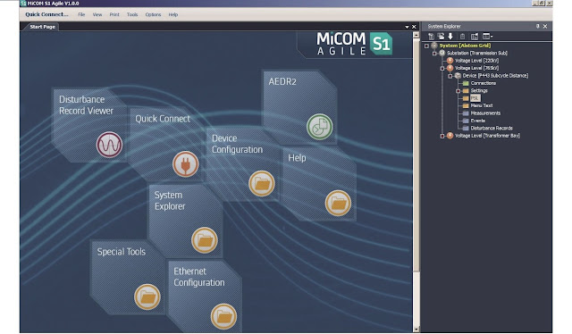
نقدم لكم في هذه التدوينة البرنامج الشهير المستخدم في برمجة ريليهات الحماية الكهربائية من الشركة العالمية السويدية ALSTOM في نسخته الحديثة.
البرنامج مقدم بنسخته الاصلية من الشركة المصنعة للحماية ALSTOM.
اضغط على الصورة لتحميل البرنامج.

شرح تنصيب البرنامج 

بعد تحميل البرنامج نقوم بالنقر عليه لتثبيته على جهاز الكمبيوتر وبعد التثبيت نقوم بعملية ادخال بيانات ريليهات الحماية وانواعها عن طريق DATA MODEL MANAGER كما هو موضح في الصور ادناه.
اتمنى ان يكون قد اعجبتكم التدونية.

للمحترفين, في مجال, الحمايات, الكهربائية, اليكم برنامج, MICOM, AGILE S1

للمحترفين, في مجال, الحمايات, الكهربائية, اليكم برنامج, MICOM, AGILE S1

للمحترفين, في مجال, الحمايات, الكهربائية, اليكم برنامج, MICOM, AGILE S1

للمحترفين, في مجال, الحمايات, الكهربائية, اليكم برنامج, MICOM, AGILE S1

للمحترفين, في مجال, الحمايات, الكهربائية, اليكم برنامج, MICOM, AGILE S1

للمحترفين, في مجال, الحمايات, الكهربائية, اليكم برنامج, MICOM, AGILE S1

للمحترفين, في مجال, الحمايات, الكهربائية, اليكم برنامج, MICOM, AGILE S1

للمهتمين بمجال الهندسة المدنية

للمهتمين بمجال الهندسة المدنية

للمهتمين, بمجال, الهندسة, المدنية


حقيبة متكاملة تحتوي على كتب دبلوم الهندسة المدنية المقدم من المؤسسة العامة للتعليم الفني والتدريب المهني  للمهتمين بمجال الهندسة المدنية والانشاءات.

للمهتمين, بمجال, الهندسة, المدنية

اضغط الصورة للتحميل


المنهج الكامل في تحضير دبلوم محركات ومركبات

المنهج الكامل في تحضير دبلوم محركات ومركبات

المنهج، الكامل، في تحضير، دبلوم، محركات، ومركبات


نقدم لكم اليوم المنهج الكامل لتحضير دبلوم محركات ومركبات قسم الميكانيكا مقدم من المؤسسة العامة للتدريب الفني والمهني حقيبة كاملة تحتوي على كتب الدبلوم كاملة للمهتمين من الاساتذة والطلاب بهذا المجال الأكثر من رائع.

 لتحميل الحقيبة اضغط على الصورة بالأعلى

دبلوم الكترونيات صناعية وتحكم

دبلوم الكترونيات صناعية وتحكم

المنهج الكامل لدبلوم الكترونيات صناعية وتحكم مقدم من المؤسسة العامة للتدريب التقني والمهني حقيبة متكاملة للمهتمين بهذا المجال لكل من الاساتذة والطلاب.
اتمنى ان تنال اعجابكم واذا اردتم المزيد ارجو عمل اعجاب ومتابعة المدونة ليصلكم المزيد والمزيد من الأشياء المفيدة.

للتحميل اضغط على الصورة>>>


كل ما يخص دبلوم الحاسب الآلي

كل ما يخص دبلوم الحاسب الآلي

لكل من يريد المنهج الشامل لدبلوم الحاسب الآلي والبرمجة الأن تستطيع تحميل جميع الكتب بصيغة PDF مقدمة من المؤسسة العامة للتدريب التقني والمهني.

اضغط على الصورة للتحميل>>>


اسطوانة المنهج الكامل في هندسة القوى POWER SYSTEM & MACHINE

اسطوانة المنهج الكامل في هندسة القوى POWER SYSTEM & MACHINE

نقدم اليكم اسطوانة تحتوى حقيبة كاملة لمنهج هندسة القوى POWER SYSTEM AND MACHINE مقدمة من المؤسسة العامة للتدريب التقني والمهني باللغة العربية تحتوى على الجزء النظري مع الجزء العملي مجموعة كاملة وشاملة في هندسة القوى وهي مقدمة لكل من الاساتذة والطلاب المهتمين بهذا التخصص اتمنى ان تنال اعجابكم.


رابط التحميل ( هـنـا ).


برنامج تصميم الدوائر الإلكترونية Multisim 10


NI MULTISIM 10 

Circuit Design Suite 
NI Multisim 10.0 & NI Ultiboard 10.0 & MCU

برنامج, تصميم, الدوائر, الإلكترونية, Multisim 10, NI MULTISIM 10   Circuit, Design, Suite,  NI Multisim 10.0, NI Ultiboard 10.0,  MCU


برنامج MultiSim لرسم الدوائر الكهربائية 

ما هو برنامج MultiSim ؟هو عبارة عن برنامج متكامل من شركة NI Electronics Workbench يهدف إلى تزويد مهندس الإلكترون ومصمم الدارات المطبوعة بمجموعة من الأدوات والآليات والعناصر التي تسمح له بالقيام بجميع عمليات التصميم والمحاكاة التفاعلية للدارات الإلكترونية .


محاكاة الدارات والتطبيق التلقائي للمخططات التمثيلية : 

لست بحاجة لأن تكون محترف أيٍّ من البرامج الهندسية المعتمدة على تقنيات وأبجديات بيئة SPICE لكي تستطيع التعامل مع برنامج MultiSim ، فهو يوفر للمستخدم بيئة بأدوات تعامل وإدراج تلقائي لعناصر وأبجديات تقنية SPICE من دون الحاجة إلى إدراجها من قبل المستخدم والذي تبقى عليه مهمة التطبيق المباشر لدارته التي يريد محاكاتها بواسطة الحاسب ، وهو يضمن الجودة المثلى لجميع خصائص عمليات القياس والمحاكاة وتسعى الشركة للتحسين والتطوير في كل إصدار لكي يتوافق البرنامج مع احتياجات الجميع . 


فبالنسبة لمصممي الدارات المطبوعة PCB يوفر البرنامج المميزات التالية : 

• بيئة تصميمية تخاطبية بين البرنامج والمستخدم في مختلف المراحل.

• عناصر تسليك وتوضيع على الدارة غير نموذجية وتتوافق مع مختلف الظروف. 

• أدوات افتراضية تفاعلية لمراقبة الإشارات الحية.

• قوالب تلقائية جاهزة لطباعة الدارات الأكثر شهرة واستخداماً .
• حفاظ على التسلسل الزمني والمنطقي لإجراءات التصميم مما يتيح إمكانية التراجع والتعديل. 
• تصدير سهل للدارة إلى برنامج UltiBoard لطباعتها . 
• استمرار لكافة المميزات في برامج طباعة الدارة ضمن قوائم منسقة وسهلة التعامل.


برنامج, تصميم, الدوائر, الإلكترونية, Multisim 10, NI MULTISIM 10   Circuit, Design, Suite,  NI Multisim 10.0, NI Ultiboard 10.0,  MCU


أدوات التصميم الإلكتروني الاحترافي : 

إنها أدوات تغطي كافة احتياجات التصميم الإلكتروني المحترف ، فهو يوفر شتى متطلبات العناصر والنظم الإلكترونية بدئاً بأجهزة القياس والإظهار و مروراً بمكتبة العناصر الإلكترونية الثرية بمحتوياتها وانتهاءاً بالمتحكمات الصغرية وأنظمة VHDL ويضعها جميعاً في عمليات محاكاة مترابطة ومتعددة المراحل التحليلية للعمل . 

• أكثر من 16 ألف عنصر إلكتروني بجميع مؤهلات التطبيق والمحاكاة المباشرة . 

• سهولة في إضافة المزيد من خصائص عملية المحاكاة ونماذجها .

• طواقم مكثفة وثرية بأنماط التحليل للدارات الإلكترونية .

التدفق الخطوي لعملية التصميم : 

باستخدام برنامج MultiSim ينتقل المصمم الإلكتروني في مراحل تصميمه من البداية وحتى مرحلة التصنيع وفق بيئة متكاملة العناصر والأدوات ، ومن الالتقاط والمحاكاة إلى الطباعة والفحص ضمن بيئة برمجية واحدة . 

حيث تقوم العناصر البرمجية للبيئة بالمهمات التالية كلاً على حدة : 

• MultiSim : التقاط المخططات والمحاكاة التفاعلية في بيئة SPICE . 

• MultiSim MCU Module : لمحاكاة المتحكمات الصغرية . 
• NI Ultiboard : لطباعة طبقات الدارة المطبوعة وخرجها وفق تقنيات التسليك والوصل المدمجة . 
• LabVIEW و SignalExpress : التحليل والقياس التفاعلي والمبرمج وفق متطلبات عمليات التصنيع ومعاييرها . 


رابط تحميل multisim v10 مع الكراك.


الرابط التحميل ( هـنـــــا )

شرح استعمال الكراك:
الكراك موجود به ملف اسمه (keygen.exe) , وهو الملف الذى سيقوم بتوليد الرخصه (license)

التى سوف تحتاجها لتفعيل البرنامج (Activation ) ... قم بالضغط عليه لتوليد الرخصه الخاصه بك .


5- سوف يقوم ال (keygen.exe) بتوليد 3 ملفات و هى :
(Multisim_ProPower_PKG_100000.lic ) --> و هذه هو الرخصه الخاصه ببرنامجMultisim
( Ultiboard_ProPower_PKG_100000.lic )--> و هذه هو الرخصه الخاصه ببرنامج

Ultiboard 
(Multisim_MCU_PKG_100000.lic )--> و هذه هو الرخصه الخاصه بتفعيل الجزء الخاص بالمايكروكونترولر( Microcontrollers ) فى برنامج Multisim ...


6- اذهب الى المجلد ( الفولدر الذى قمت بتسطيب برنامج اليكترونكس ورك بنش فيه ) فى مجلد ( programs File و قم بانشاء مجلد جديد New Folder و سميه License


7- قم بنسخ الثلاث ملفات السابقه فيه .


8- اذهب الى قائمة ابدأ ( Start Menu ) .. ثم All programs ثم National Instruments ثم

اختار NI License Manager 


9- اختار Multisim 10.0 ثم اضغط F8 ستظهر لك نافذه تطلب منك تحديد مكان ملف الرخصه لل Multisim ... قم بتحديد مكان ملف الرخصه و هى Multisim_ProPower_PKG_100000.lic


10 - كرر نفس الخطوه السابقه و لكن هذه المره اختار ملف الرخصه Multisim_MCU_PKG_100000.lic و ذلك لتفعيل الجزء الخاص بالمتحكمات الدقيقه(microcontrollers ) فى برنامج Multisim


11 - اختار Utiboard ثم اضغط F8 ستظهر لك نافذه تطلب منك رخصه البرنامج (license ) ..قم بتحديد مكان ملف الرخصه و هو Ultiboard_ProPower_PKG_100000.lic الموجود فى فولدر License.


اتمنى ان يحوز موضوع اليوم على اعجابكم،،،